viewof sigma1 = Inputs.range([20, 300], {value: 150, step: 1, label: "σ₁ — greatest principal stress (MPa)"})
viewof sigma3 = Inputs.range([0, 200], {value: 50, step: 1, label: "σ₃ — least principal stress (MPa)"})
viewof pf = Inputs.range([0, 200], {value: 20, step: 1, label: "Pf — pore fluid pressure (MPa)"})Crustal stress, faulting and fluid flow
paper-discussion
fault-mechanics
crustal-stress
fluid-flow
Paper details
Citation
Sibson, Richard H. 1992. “Crustal Stress, Faulting and Fluid Flow.” Geological Society, London, Special Publications 78: 69–84.
Abstract
Differential stress exerts both static and dynamic effects on rock-mass permeability, modulating fluid flow in the Earth’s crust. Static stress fields impose a permeability anisotropy from stress-controlled features such as faults, extension fractures, and stylolites which, depending on the tectonic regime, may enhance, or counteract existing anisotropic permeability in layered rock sequences. Textural evidence from hydrothermal veins suggests, however, that fluid flow in fault-related fracture systems generally occurs episodically and that dynamic stress cycling effects are widespread. In the vicinity of active faults that undergo intermittent rupturing, permeability and fluid flux may be tied to the earthquake cycle through a range of mechanisms, leading to complex interactions between stress cycling, the creation and destruction of permeability, and fluid flow. Mechanisms for fluid redistribution include: (1) various forms of dilatancy (localized to the fault zone or extending through the surrounding rock mass) related to changes in shear stress and/or mean stress that occur during the fault loading cycle; (2) localized post-seismic redistribution around rupture irregularities, especially dilational jogs and bends which act as suction pumps; and (3) post-seismic discharge of fluids from overpressured portions of the crust through fault-valve action when ruptures breach impermeable barriers. All of these processes may be involved in fluid redistribution around active faults, but they operate to varying extents at different crustal levels, and in different tectonic regimes.
Presentation summary
Takeaway
Crustal stress controls both where fluids can flow (permeability geometry) and whether faults slip (via effective stress). Fluid flow through fault zones is fundamentally episodic — driven by the earthquake cycle, not steady-state gradients. Stress cycling is the great modulator of fluid flow in the deforming crust.
Background: a brief stress primer
NoteKey concepts
The crust is described by three principal stresses (σ₁ ≥ σ₂ ≥ σ₃). Their orientations define the tectonic regime (thrust: σ₁ horizontal; normal: σ₁ vertical; strike-slip: σ₁ and σ₃ horizontal). On a fault plane these resolve into normal stress σₙ (clamping) and shear stress τ (driving slip).
Effective stress: pore fluid pressure Pf directly reduces the clamping force — σ’ₙ = σₙ − Pf — so fault strength becomes:
\[\tau_r = C + \mu_s(\sigma_n - P_f)\]
The pore-fluid factor λᵥ = Pf/σᵥ measures overpressure: λᵥ ≈ 0.4 hydrostatic; λᵥ → 1.0 lithostatic (sealed compartment). Raising Pf shifts the Mohr circle left toward failure without changing its size.
Dilatancy primer
Dilatancy is volume increase under increasing differential stress — a fundamentally deviatoric phenomenon, not isotropic loading. As shear stress builds, microcracks open perpendicular to σ₃; at ~50–80% of failure stress, crack volume grows faster than elastic compaction, so the rock swells slightly under compression. A dilating zone that drains slowly develops transient underpressure, drawing fluids in; post-failure crack closure expels them.
This was the basis of the dilatancy-diffusion hypothesis (Nur 1972; Scholz et al. 1973) and Sibson’s own seismic pumping model (1975): interseismic dilatancy draws fluids toward the fault; fluid diffusion back in triggers failure; post-seismic crack closure expels fluids upward. The model predicted Vp/Vs anomalies before earthquakes. It failed — it requires τ > 100 MPa across a broad rock volume, far above likely crustal stress levels, and stress perturbations decay too rapidly with distance (~1/r) to sustain regional dilatancy. What survives is a geometrically localised version: sharp mean-stress drops at dilational jogs and bends during rupture propagation (see Key Theme 3).
Geological evidence base
Hydrothermal vein systems
- Volume: Mother Lode (Sierra Nevada) requires >10⁸ m³ fluid/km fault strike to deposit the observed quartz — a supergiant oil field’s worth of water per kilometre
- Texture: crack-seal microstructures and ribbon veins record hundreds of episodic opening events, not steady flow
- Geometry: flat extension vein arrays (pre-failure hydrofracture) cross-cut by steep fault-veins (post-failure discharge conduits) — direct structural record of the valve cycle
Post-seismic hydrology
- Borah Peak 1983 (M7.3): ~0.3 km³ fluid discharged over months post-rupture, including surface fountaining along the rupture trace
Fault weakness — the San Andreas
- No heat-flow anomaly → time-averaged shear resistance <20 MPa (far below Byerlee prediction)
- Fault at 65–85° to σ₁ → mechanically misoriented; both observations independently require near-lithostatic Pf
Extension veins as fluid pressure gauges
- Vertical veins → Pf > σ₃ (horizontal stress); flat-lying veins → Pf > σᵥ (near-lithostatic)
- Panasqueira, Portugal: flat vein array 4 × 3 km, 1 km deep — requires seal tensile strength ~10–20 MPa
- Caveat: no extension veins ≠ no overpressure — on a well-oriented cohesionless fault, reshear always occurs before hydraulic fracturing
NoteA note on the evidence
Sibson is explicit that constitutive laws for dilatancy are unresolved and critical parameters are poorly constrained. The geological evidence motivates the models but does not uniquely determine them.
Key themes
1. Stress field controls permeability geometry
- Extension fractures (⊥ σ₃) → conduits; faults (~20–30° to σ₁) → transiently permeable post-rupture; stylolites (⊥ σ₁) → barriers
- In layered sequences: compression enhances bedding-parallel flow; extension enhances cross-bedding (vertical) flow
- Hill fault/fracture meshes — interlocking shear + extension fractures — are the most efficient conduits; the Mother Lode vein system is the classic example
2. Fault permeability is transient
Continuous competition between fracture creation (rupture) and destruction (hydrothermal sealing, gouge, pressure solution) makes fluid flow inherently episodic — constant-permeability models cannot account for observed vein volumes.
3. The earthquake cycle drives fluid redistribution — three mechanisms
Dilatancy pumping (pre/post-seismic): differential stress loading opens microcracks → fluids drawn in; post-failure crack closure → fluids expelled. Effect is larger for normal/strike-slip (load-weakening) than thrust faults (load-strengthening).
Suction pumping at dilational jogs (co/post-seismic): irregular fault geometry produces abrupt mean-stress drops at dilational bends during rupture propagation → rapid fluid influx. Favoured sites for aftershocks and mineralisation.
Fault-valve action (compressional regimes): sealed overpressured compartment (λᵥ → 1) → rupture breaches seal → rapid upward discharge → hydrothermal self-sealing → pressure rebuilds → repeat. Explains mesothermal Au-quartz lodes in steep reverse faults.
Why it matters for ERG
- Induced and triggered seismicity: injecting fluid raises Pf → lowers σ’ₙ → existing faults move closer to failure. The same logic applies to co-seismic fluid redistribution triggering remote aftershocks
- Fault strength: near-lithostatic fluid pressure is the leading explanation for “weak” faults like the San Andreas; stress and fluid pressure are inseparable in fault mechanics
- Hydrothermal mineralisation: mesothermal gold deposits (including Lachlan Fold Belt examples) are essentially fossilised fault-valve systems — structural position relative to the stress field is a first-order exploration guide
- Rupture nucleation and recurrence: fluid pressure cycling tied to fault-valve action makes both the timing and location of rupture time-dependent, with fault strength reaching a minimum just before failure
From the talk: additional themes
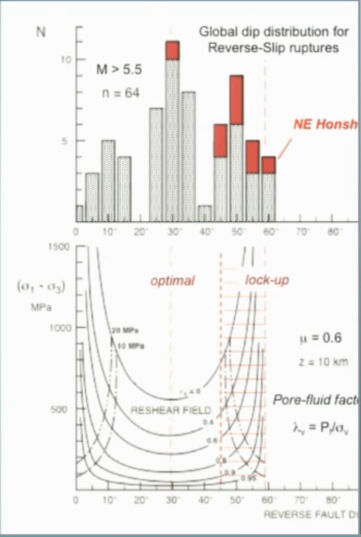
Fault lockup and the reactivation angle
At θᴿ ≈ 60° to σ₁ (the frictional lockup angle for μ = 0.75), a fault cannot slip unless Pf reaches σ₃. The dip distribution of active reverse fault ruptures peaks at ~30° and extends to ~55–60°, with the high-dip cases implying λᵥ ~ 0.8–0.9. This is especially evident in northern Honshu, where compressional inversion forces rupture on inherited near-lockup normal faults — bright-spot reflectors and high-conductivity zones near hypocentres are interpreted as overpressured fluid arrays. Ninety percent of global seismic moment is released on subduction megathrusts where λᵥ ≥ 0.9–0.95; the overpressured fault is the global norm.
Load strengthening vs load weakening
Thrust loading increases mean stress as shear stress rises → load-strengthening (frictional resistance grows during loading; failure is abrupt). Normal fault loading decreases mean stress → load-weakening (resistance falls as loading proceeds; failure more gradual). This partly explains why foreshock sequences are more common around normal fault earthquakes, and why reverse fault ruptures tend to release more stored strain energy.
Fault glass and thermal pressurisation
Frictional heating at seismic slip rates should melt all faults. The Outer Hebrides Thrust has pseudotachylyte; the Moine Thrust — studied exhaustively for over a century — has none. In fluid-saturated rocks, rapid pore-pressure rise during slip (thermal pressurisation) quenches frictional resistance before melt temperatures are reached. Pseudotachylyte may mark dry, immature fault zones rather than anomalously high stress.
Interactive: Mohr circle explorer
Use the sliders to change the principal stresses and pore fluid pressure. The Mohr circle shifts left as fluid pressure increases — watch how it approaches the failure envelope without changing size (the size depends only on differential stress, σ₁ − σ₃).
The 4T limit: shear vs extension failure
Raising Pf moves the Mohr circle left. Which part of the failure envelope it hits first depends on the size of the circle — i.e. the differential stress:
\[(\sigma_1 - \sigma_3) < 4T \;\Rightarrow\; \text{extension fracture (Mode I, perpendicular to } \sigma_3 \text{)}\] \[(\sigma_1 - \sigma_3) > 4T \;\Rightarrow\; \text{shear failure (Coulomb)}\]
For typical crustal rocks T ≈ 5–15 MPa, so 4T ≈ 20–60 MPa. In a sandstone–shale sequence where T_sandstone > T_shale, the same differential stress can push shales into Coulomb shear while sandstones still satisfy the extension fracture condition — producing the interlocking fault/fracture mesh of shears and veins that acts as a highly efficient fluid conduit.
Session resources
Media
R.H. Sibson — “Crustal stress, faulting and fluid flow” (GNS Science lecture) Watch on YouTube — cued to the fault mechanics section.
Group Discussion
Discussion questions
- Sibson argues that fluid flow in fault zones is fundamentally episodic rather than steady-state. What geological evidence would you look for to distinguish between these two modes in the rock record?
- The fault-valve model predicts that rupture on a reverse fault should be accompanied by upward fluid discharge and rapid hydrothermal sealing. Can you think of any modern seismic sequences where this signature has (or hasn’t) been observed?
- Fluid overpressure is proposed as the explanation for the anomalous weakness of the San Andreas Fault. What are the alternatives, and is there a way to test between them?
- The paper was written in 1992. Which of the three fluid redistribution mechanisms (dilatancy pumping, suction pumping, fault-valve action) do you think has received the most support from subsequent work, and why?
- Sibson argues that thrust faults are load-strengthening and normal faults are load-weakening. What observable differences in earthquake behaviour (foreshocks, aftershocks, stress drops, rupture style) would you predict from this asymmetry, and is there evidence for it?
Discussion (via GitHub)
The discussion for this session lives in the comments below.
Add thoughts, references, data links, or follow-up questions — this stays as a running record for the group.
(GitHub login required the first time.)